My Store
MORA ground robot Type13 frame kit
MORA ground robot Type13 frame kit
Couldn't load pickup availability
1. Packaging BOM
- Controller cabin top plate*1
- Controller cabin middle plate*1
- Controller cabin bottom plate*1
- Internal reinforcement ribs*4
- Leg B part*4
Screw kit:
- M2 * 4mm * 2(fix network camera module)
- M2 * 6mm * 8(Fix the H743 development board module)
- M2 * 8mm * 4(Fix image transmitter and signal transmitter)
- M3 * 8mm * 16(Fix leg B parts and bearings)
- M3 * 12mm * 30(Fix shell plate)
- M3 * 18mm * 6(Fix servos)
- M3 * 20mm * 4(Fix Compute Module)
- M3 * 28mm * 4(Fix the Motor Driver Module)
Print part kit:
- Network camera mount*1 pair
- Network antenna mount*1
- Telemetry antenna mount*1
Silicone shock pad*1
cable tie*2
2.Improved structural description

In previous V1 versions, aluminum alloy was used to make the legs and controller compartment(GPU, MCU H743 development board, FOC motor drivers).It is planned to make the controller cabin into an integrated module to facilitate disassembly, assembly and maintenance.Composite materials will also be used to produce the extended legs and controller cabin.According to our calculations, if the extended legs do not use carbon fiber materials, the estimated weight is 7.6kg. If a carbon fiber modular controller cabin and carbon fiber legs are used, the overall weight will be reduced by about 2kg, and the overall weight will be 5.6kg.

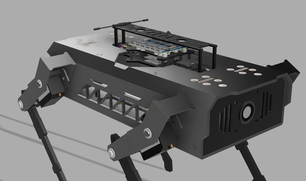
A complete rendering of the improved robot dog(Front 45 degree view).Independent electrical compartment to improve expandability and maintenance convenience.The extended carbon fiber legs are beneficial to improving wear resistance and passability, and reducing overall weight.

Rear 45 degree view.The telemetry antenna can be seen in the picture,It is located at the rear end of the upper plate of the controller cabin.The FOC motor drivers are located above the controller compartment, and the H743 main controller is located below the FOC motor drivers.Considering the complex structure needed to fix joint servos,the main body and the upper two sections of the legs use the original aluminum alloy parts.

The camera front plate is produced using 3D printing to be compatible with network camera modules of different models and zoom ratios.After the front board is removed, the camera mount and camera module can be removed.


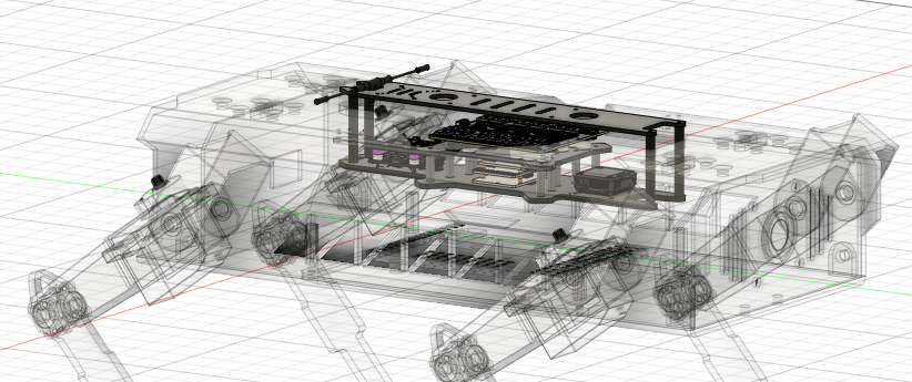
Schematic diagram of the location and fixing method of the controller compartment in the fuselage.Integrating the motor controller and all the main controllers in the electrical compartment facilitates user maintenance and debugging, as well as the freedom to replace other models of controllers without having to remove the aluminum alloy protective plate of the fuselage.


Overall schematic diagram of the carbon fiber leg and partial installation schematic diagram.The accuracy of the mounting holes must be within the range of plus or minus 0.05 mm.The circular hole where the carbon fiber arm and the second joint bearing are connected needs to be chamfered with a chamfer depth of 0.5mm.In addition, the inner wall where the joint is connected needs to be polished to ensure that the joint bearing and the carbon fiber leg fit closely.

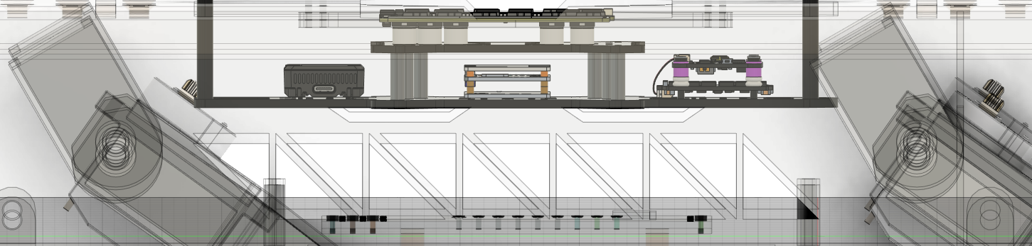
Schematic diagram of the carbon fiber reinforced connecting rods inside the fuselage.Considering that the modular controller cabin is not tightly fixed inside the fuselage, it is necessary to add two transverse support rods and two longitudinal support rods inside the fuselage to provide strength for the entire fuselage, as well as to fix and support the controller cabin.When processing the support rod, it is necessary to pay attention to the accuracy of the sinking part and the opening diameter in the drawing, which is plus or minus 0.05mm.