
MORADIY
MORA ground robot Type10 frame kit
MORA ground robot Type10 frame kit
Couldn't load pickup availability
1. Packaging BOM
Controller cabin top plate*1
Controller cabin middle plate*1
Controller cabin bottom plate*1
Leg B part*4
Screw kit:
M2 * 4mm*2(fix network camera module)
M2 * 6mm*4(Fix the H743 development board module)
M3 * 8mm*16(Fix leg B parts and bearings)
M3 * 10mm*14(Fix shell plate)
M3 * 16mm*6(Fix servos)
M3 * 18mm*4(Fix Compute Module)
M3 * 28mm*4(Fix the Motor Driver Module)
Print part kit:
Network camera mount*1 pair
Network antenna mount*1
Telemetry antenna mount*1
Silicone shock pad*1
cable tie*2
2.Model V3 improved structural description
The V3 small robot dog and neutral robot dog are created using a new
generation of design concepts. That is, using an integrated controller cabin and
carbon fiber legs to improve the robot's overall performance and reduce its
weight. According to our calculations, For the small V3 model, the use of
carbon fiber legs and carbon fiber controller pod reduces the overall weight
from 5.5kg to 3.7kg.

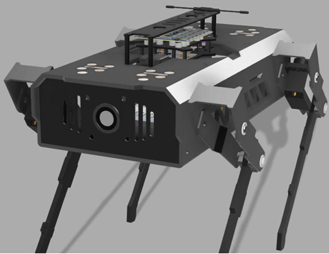
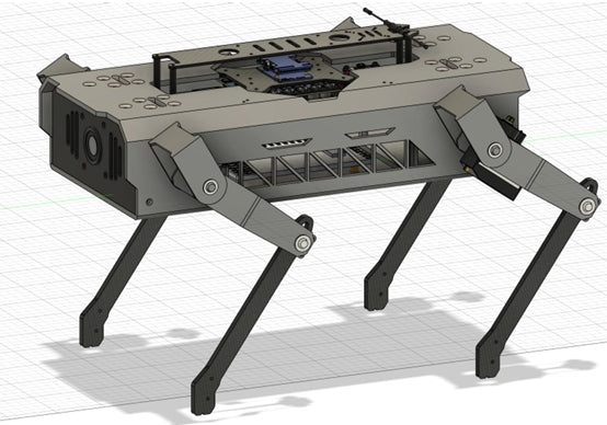
Acomplete rendering of the improved V3 model robot dog(Front 45 degree
view). Independent electrical compartment to improve expandability and
maintenance convenience. The carbon fiber legs are beneficial to improving
wear resistance, and reducing overall weight.
The camera front plate is produced using 3D printing to be compatible with
network camera modules of different models and zoom ratios. After the front
board is removed, the camera mount and camera module can be removed.


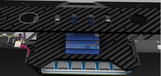
Schematic diagram of the location and fixing method of the controller
compartment in the V3 fuselage. Integrating the motor controller and all the
main controllers in the electrical compartment facilitates user maintenance and
debugging, as well as the freedom to replace other models of controllers
without having to remove the aluminum alloy protective plate of the fuselage.


Overall schematic diagram of the carbon fiber leg and partial installation
schematic diagram. The accuracy of the mounting holes must be within the
range of plus or minus 0.05 mm. The circular hole where the carbon fiber arm
and the second joint bearing are connected needs to be chamfered with a
chamfer depth of 0.5mm. In addition, the inner wall where the joint is connected
needs to be polished to ensure that the joint bearing and the carbon fiber leg fit
closely